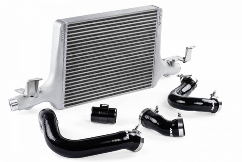
• APR INTERCOOLER SYSTEM For Audi B9 SQ5 3.0 TFSI - IC100026
  • APR INTERCOOLER SYSTEM For Audi B9 SQ5 3.0 TFSI - IC100026
  • APR INTERCOOLER SYSTEM For Audi B9 SQ5 3.0 TFSI - IC100026
  • APR INTERCOOLER SYSTEM For Audi B9 SQ5 3.0 TFSI - IC100026
  • APR INTERCOOLER SYSTEM For Audi B9 SQ5 3.0 TFSI - IC100026
  • APR INTERCOOLER SYSTEM For Audi B9 SQ5 3.0 TFSI - IC100026
  • APR INTERCOOLER SYSTEM For Audi B9 SQ5 3.0 TFSI - IC100026
  • APR INTERCOOLER SYSTEM For Audi B9 SQ5 3.0 TFSI - IC100026
  • APR INTERCOOLER SYSTEM For Audi B9 SQ5 3.0 TFSI - IC100026
  • APR INTERCOOLER SYSTEM For Audi B9 SQ5 3.0 TFSI - IC100026
  • APR INTERCOOLER SYSTEM For Audi B9 SQ5 3.0 TFSI - IC100026
  • APR INTERCOOLER SYSTEM For Audi B9 SQ5 3.0 TFSI - IC100026
  • APR INTERCOOLER SYSTEM For Audi B9 SQ5 3.0 TFSI - IC100026

APR INTERCOOLER SYSTEM For Audi B9 SQ5 3.0 TFSI - IC100026

Free Shipping*

On Sale

Was: $1,406.95
Now: $1,124.96
UPC:
00810009933083
Adding to cart… The item has been added
Order now and you should receive this item between Wednesday and Friday

Verify fitment with your vehicle


WARNING: This product can expose you to chemicals that are known to the State of California to cause cancer, birth defects or other reproductive harm. For more information, visit www.P65warnings.ca.gov.


The APR Intercooler System is a massive front mounted upgrade that dramatically reduces intake air temperature (IAT), minimizes heat soak, and provides increased performance! The system is an easy to install, direct bolt-on design, that is recommended at every stage of performance.

Features:

  • Dramatically lowers intake air temp (IAT)
  • The factory intercooler reaches dangerously high IAT levels, even on the stock ECU!
  • Massive frontal surface area and core volume
  • 3.125" x 5.75" x 28.25" - 162.4 in² front. & 507.62 in³ volume - OEM
  • 2.250" x 16.2" x 22.00" - 356.4 in² front. & 801.90 in³ volume - APR
  • Highly effective core design
  • Bar-and-plate core with staggered and louvered fins.
  • Rigorous testing determined core style, fin density, and size.
  • Low pressure drop + highly effective cooling = high performance!
  • Smooth cast end tanks Engineered for low turbulence/restriction and maximum flow.
  • Organically shaped to promote airflow across entire core.
  • Pressure tested to prevent power robbing boost leaks.
  • Easy to install
  • Simple plug-and-play design with no trimming or drilling necessary!
  • Designed by engineers with lasers
  • With the best equipment and smartest engineers, it just works!

Dyno Testing


Design


Unfortunately, to the untrained eye, many intercooler designs appear the same. However, effectiveness of the system and overall performance are greatly determined by several key metrics. Alloy selection, end tank design, construction type, fin style, fin density and overall core dimensions must be analyzed and balanced accordingly to deliver class-leading performance. While the OEM’s goal is to create a lightweight, easy to manufacture and inexpensive to produce, cross-platform design capable of supporting factory power levels, APR’s intercooler must be capable of supporting more than factory output. Achieving this goal took a multi-step approach focused around intercooler core selection, end tank design and install location.


Intercooler Core Design

The APR Intercooler core is a large bar-and-plate design featuring densely packed staggered and louvered fins. This design offers exceptional cooling while balancing pressure loss across the core, and maintaining critical airflow to the components behind the intercooler system. The core size was appropriately matched to the platform, minimizing pressure drop while leaving adequate space for appropriately designed end tanks. To APR’s mechanical engineering experts, the design represented the ultimate in performance, far exceeding the capabilities of the factory intercooler. To the driver, the result is simple: Repeatable performance, even in the most demanding of situations!


Core Style / Internal Fin Structure:


APR’s Engineers paid close attention to the balance between core effectiveness and pressure drop through the core, core style and fin density. With fin density too low, pressure drop decreases dramatically, but typically results in a core incapable of effectively cooling. Likewise, with fin density too great, pressure drop increases dramatically, resulting in the turbocharger working harder, and hotter, to produce the same level of airflow. By fine tuning this often unseen balancing act, as illustrated below, APR’s Engineers were able to maximize performance.


Core Styles


# TYPE FINS DENSITY PSI DROP EFFECTIVENESS COST COMMENTS RECOMMENDATIONS
1 TUBE AND FIN STRAIGHT CHANNEL LOW LOW LOW  $ POOR COOLING NOT RECOMMENDED
2 BAR AND PLATE STRAIGHT CHANNEL LOW LOW LOW $$ POOR COOLING NOT RECOMMENDED
3 QUALITY BAR AND PLATE STAGGERED AND OFFSET MEDIUM MEDIUM HIGH $$$ EXCELLENT COOLING RECOMMENDED
4 OVERLY DENSE BAR AND PLATE STAGGERED AND OFFSET HIGH HIGH HIGH $$$ EXCESSIVE PRESSURE DROP NOT RECOMMENDED


Core Size:


APR’s Engineers also paid close attention to the balancing act between core effectiveness, pressure drop and space for end tanks through core sizing. With the core too small, pressure drop decreases dramatically, but typically results in a core incapable of effectively cooling. Likewise, with core size too great, pressure drop can increase, resulting in the turbocharger working harder. However, more importantly, with no space for appropriate end tanks, utilization of the core and overall effectiveness of the system diminishes rapidly, negating the benefit of the larger core. APR’s engineers were able to balance each of these characteristics to deliver maximum performance. The APR system increases frontal surface area by 119.09% and has a 58% larger core!


Core Specs


SYSTEM TYPE THICKNESS WIDTH HEIGHT VOLUME FRONTAL AREA
OEM TUBE AND FIN 3.125" 28.25" 5.75" 507.62 IN³ 162.4 IN²
APR BAR AND PLATE 2.25" 22" 16.2" 801.9 IN³ 356.45 IN²


Intercooler End Tank Design


To fully utilize the massive core, APR’s mechanical engineers designed cast aluminum end tanks organically shaped for proper airflow distribution across the entire core. By correctly sizing the intercooler core, end tank design was not sacrificed. The one-piece end tanks are CNC machined to provide a slip resistant mounting surface for hoses, precise integrated mounting surfaces, and perfectly flat connecting surfaces used for TIG welding the tanks to the core. Through proper alignment in welding jigs, each unit is assembled to tight tolerances for a precise and accurate fit.


Intercooler Bracket Design


APR’s mechanical engineers designed CNC-bent and TIG-welded mounting brackets to securely hold the intercooler in place. The brackets make the install extremely easy. With the bumper and factory intercooler unit removed, the APR intercooler installs in minutes without any cutting, drilling or trimming. For the DIY customer, this makes a home install simple, and for everyone else it eliminates hidden costs that often come with a more labor intensive install.


Intercooler Hoses and Clamps


The APR Intercooler System includes the highest quality silicone inlet and outlet hoses, T-bolt clamps and billet MAP housing. Each component is designed to protect against boost leaks at extreme pressures, and stand the test of time.


Hoses: The hoses are constructed from multi-ply silicone, and are wire-reinforced to prevent swelling and bursting at extreme boost pressures. Internally, the hoses are lined with fluorosilicone to protect the hoses from oil and gasoline deterioration. Finally, each hose feature’s APR’s EZ-Flow stepped design to provide a smooth airflow path at the hose transition points.


Clamps: Strong Clampco T-bolt clamps are used throughout, replacing the factory worm-gear clamps. The clamps are made from stainless steel, and are of a high-quality and high-strength design that diminishes the risk of boost leaks. Lastly, the clamp’s thick clamping style provides increased connection strength, and decreased hose slippage compared to other styles of clamps.


MAP Housing: A billet MAP sensor housing provides a secure mounting point for the factory pre-throttle MAP sensor. The precision cnc-machined housing helps to prevent leaks around the sensor, and the matte-black anodizing gives the housing a clean and attractive look within the engine bay.


Testing


APR’s engineers tested each intercooler in a multitude of tests to show the impact the APR intercooler has on intake air temperature. The following tests were conducted with a 2017 S4 using the stock ECU calibration on 93 octane fuel and no other modifications. Ambient conditions during the stock intercooler tests were 72.8°F and 98.4 kPa with 78.7% relative humidity. Conditions were similar later in the day during during the APR Intercooler testing with 78.4°F and 98.5 KPa with 62.8% relative humidity. This gave the APR Intercooler no added advantage over the stock system during the tests. First, six back-to-back dyno pulls were conducted with each intercooler. Each run was conducted in 4th gear, from idle to redline, with a cool down between runs. The stock intercooler failed to combat rising IAT’s and quickly exhibited power-robbing heat soak. IAT’s started at 35°C and quickly rose to 60°C by the end of the first dyno pull. This trend continued with the final dyno pull reaching a staggering 67°C! In contrast, the APR Intercooler only reached 34°C by the end of the first dyno pull. It was then able to continue rejecting heat, only reaching 36°C by the end of the final dyno pull. The APR Intercooler performed better after 6 back-to-back dyno pulls than the factory intercooler did on it’s very first dyno pull. Next we tested a 10-135 second sprint through the gears. With the factory intercooler, IAT quickly rose from a starting temperature of 32°C to a blistering 81°C! It was so bad, we had to abort the test as we felt it was too dangerous to continue further. However, as expected, the APR intercooler handled IAT’s extremely well. With a starting temperature of 29°C, IAT slightly climbed above the starting temperature to 42°C by the end of the sprint. A difference of 39°C was exhibited between the two units after only a single top speed. This directly translates to faster acceleration, and better performance in all conditions.


Only use fuel equal to or higher than specified. Never use a lower octane fuel. Always follow our fuel guide, especially with race fuel and Ethanol, where available. Dynos are for reference only. Results will vary. Contributing factors include the vehicle condition, vehicle setup, dyno type, dyno setup, environmental factors, fuel quality, and more. When describing fuels, the North American Region (NAR) uses the Anti-Knock Index (AKI), (RON+MON)/2, or (R+M)/2. The Rest of the World (ROW) uses RON. RON is Research Octane Number and MON is Motor Octane Number.


This part is legal for sale or use on Racing Use Only Vehicles


The following vehicles are considered Racing Use Only Vehicles:

  • Racing Use Only Vehicles are vehicles that are used exclusively for competition that are not registered and that may never be used on the street.

PDP tag:
Free Shipping*
Sales:
On Sale
PDP tag:
On Sale

Reviews